Tag: paper

Paper and Cardboard Streams Germany 2013

German Environment Protection Agency (Umweltbundesamt, UBA) has published the final report of its project “Resource conservation through material flow-oriented secondary raw materials management” (German: “Stoffstromorientierte Ermittlung des Beitrags der Sekundärrohstoffwirtschaft zur Schonung von Primärrohstoffen und Steigerung der Ressourcenproduktivität”).

The study had been commissioned to three research institutes that were tasked to “analyse the Federal Statistical Office’s waste statistics … and carry out detailed investigations for 30 materials with focus on determining the recovery routes of these secondary raw material quantities and their derived substitution potentials.”

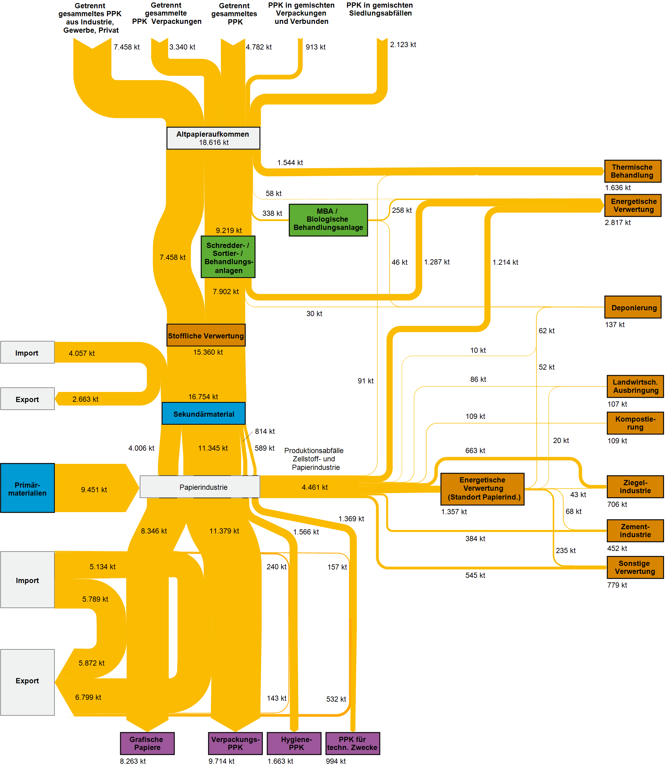
The report is gold for Sankey diagram aficionados: For all of the thirty materials analysed we can find Sankey diagrams depicting the streams through the economy and different recycling paths and secondary use options. Here is an example for paper and cardboard.

Flows are in kilo tonnes (kt) of material in 2013 in Germany. Inputs at the top are sources of paper fibres from waste collection. The general direction of flow is top-to-bottom with energetic use and reuse in other industries branching out to the right (brown boxes). Imports come in from the left and exports leave to the left again. Interesting to see, for example, that exports of graphical paper products almost exactly match the imports, while packaging paper exports (see stream to purple box “Verpackings PPK”) are slightly higher.

Beautifully crafted Sankey diagrams. A pity this isn’t available in English, but for those who love these self-speaking diagrams, here is the link to access the full report. Enjoy!
Global Paper Flows Sankey Diagram

Researchers from the Institute for Sustainable Resources (ISR) and the Center for Resource Efficiency & the Environment (CREE) at the University College London (UCL) have set up this Sankey diagram of global material flows in the paper life cycle, from primary inputs to end-of-life waste treatment.

Flows are in megatonnes based on data for 2012. We can see the five phases in the paper life cycle, from wood harvest over pulping, paper making, to use and discard/end-of-life. Almost half of the paper used and discarded worldwide in 2012 was recycled (194 Mt out of 399 mt). However, 154 Mt of used paper still ended up on landfills.

The authors further discuss environmental performance metrics. They point out that looking only at the recycling rate may lead to a wrong impression. They propose to also consider another recycling metrics (recycled input rate, RIR), and a material efficiency metrics.

The paper ‘Global Life Cycle Paper Flows, Recycling Metrics, and Material Efficiency’ by Stijn Van Ewijk, Julia Stegemann, and Paul Ekins has been published in the Journal of Industrial Ecology. A summary can be found here, or access the full article at Wiley Online Library (Open Access under Creative Commons license).

Thanks to the author Stijn van Ewijk for pointing me to this recent publication.

Paper Factory Wastewater, Patent

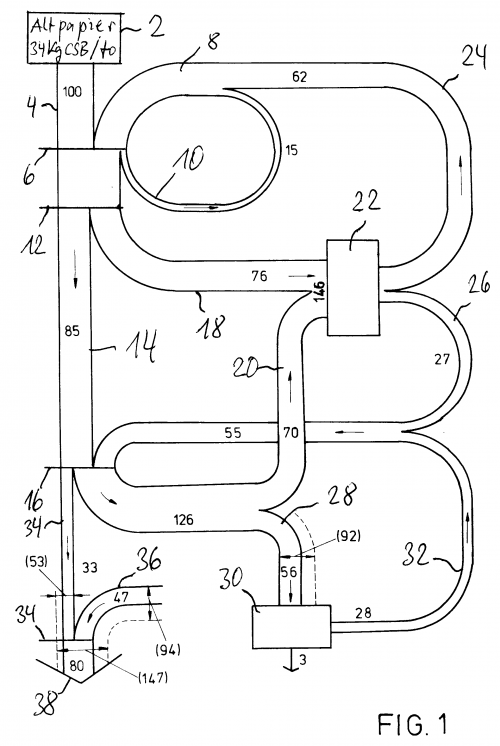
Browsing Google Patents can be fun, if you like long sentences… It also sometimes reveals a hand-drawn Sankey diagram, like this one:

This is from a patent filing EP 0494399 A1 on “Process to direct and treat production waters in a paper factory with installation for treatment of waste paper” by German inventor Wilhelm Menges.

The diagram is for a paper recycling process. The “thickening filtrate arising from the dispersion of waste paper is directly fed to a biological waste water” treatment. This reduces the COD levels.

Flow quantities are shown in printed numbers. A lot of hand-written numbers refer to process elements.

Paper Machine Enthalpy Sankey Diagram

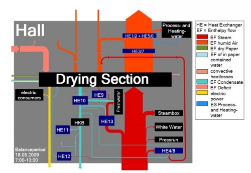
A research project at Technical University Dresden in collaboration with a paper manufacturer aims at detecting and implementing energy saving measures for paper machines.

“Better monitoring of process variables, improvement in the operating point (or range) of the process, installation of heat recovery systems (e.g. at heat exchangers), use of heat pumps and replacement of high energy streams (steam) with waste heat streams. Most of these techniques are standard recipes which are readily available in the market. However they are designed without giving any consideration to the specific aspects of a manufacturing facility and also provide no quantitative evidence of the potential benefits. “

This is why they came up with a mass and energy balance model and are using the following Sankey diagram to visualize where energy could be recovered.


Flows are labeled as enthalpy flows, showing the changes in thermodynamic (heat) energy at each process step, hence losses. The Sankey diagram is for a balance period of six hours. No absolute figures are given. Several heat exchangers are installed along the wet section of the paper machine. In the drying section, a large part of the energy is lost as steam/humid air.

Energy Recovery from Process Air

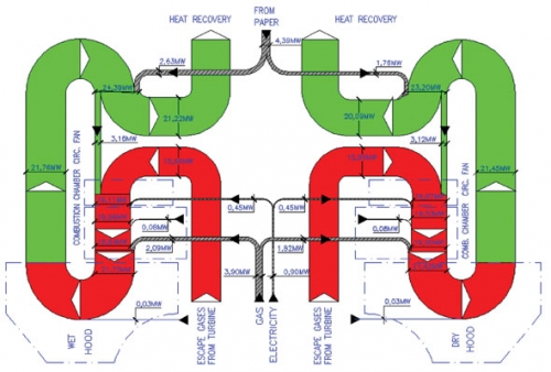
This article on “Energy Savings in Tissue Production Process: The Case of the Hayat Tissue Mill in Turkey” by A. Isiklar, L. Aydin, D. Mainardi and O. Lopez was published in July 2008 in the TAPPSA Journal (Technical Association of the Pulp and Paper Industry of the Southern Africa). The article describes how energy can be recovered from process air in a tissue plant in Turkey using a cogeneration hood. It features three beautiful Sankey diagrams, one of which is presented here.

“The exhaust gases coming from the hood are used for the production of the steam needed to feed the YD and the other auxiliary equipment of the mill (wet strength pulper, hall ventilation). The residual energy in exhaust gases in excess from the boiler are used in order to feed a chiller unit, which in turn runs the air conditioning system of the electrical room”.

This almost symmetric top to bottom oriented diagram shows the energy in MW for a certain production capacity (details not given in the article). It is a section of the other Sankey diagram featured in the article (Fig. 3) showing the whole process including the gas turbines plant, the cogeneration hood and the waste heat boilers (omitting only the absorption chillers). Only the latter shows the reduced heat loss (see light blue arrows labeled “to atmosphere”).

As for me, that’s the kind of curves I love… 😉