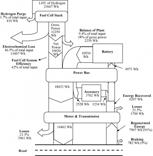
From a project summary on the webpage of the Fuel Cell Research Lab at University of Delaware’s Department of Mechanical Engineering comes this Sankey diagram.
This is for a bus operating on the University of Delaware campus. The Sankey diagram shows energy flow and losses in the hybrid power train for a typical drive cycle. Unit is Wh, percentages are given in the labels as additional information. Energy is recovered when braking and is fed back to the battery (see upstream arrow ‘Energy Recovery’).
“The fuel cell system balance of plant consumes a significant fraction of the energy of the hydrogen supplying the stack, so efficiency gains there are potentially quite useful. Most of the balance of plant energy feeds the air compressor, so efficiency could be increased by improving air humidification to allow lower air system backpressure”
Simple black and white diagram with a top-down orientation. The only extra that does not serve to carry information is the schematic road figuring at the bottom….
For the full publication check Bubna P., Brunner D., Gangloff Jr. J.J., Advani S.G., and Prasad A.K., “Analysis, operation, and maintenance of a fuel cell/battery series-hybrid bus for urban transit applications,” Journal of Power Sources, Vol. 195, pp. 3939-3949, June 15, 2010. doi:10.1016/j.jpowsour.2009.12.080


