Phosporus in the natural environment and the food chain has been a topic of several posts on my blog. So it didn’t come as a surprise to find yet another diagram on phoshphorus flows over at Nels’s MFA Diagram blog (one of the blogs I follow closely, see blogroll).
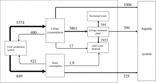
MFA diagrams have their focus on the nodes and the build-up of stocks. Sometimes they get a touch of Sankey diagram with the arrows having different magnitudes. The MFA diagram below is for phosphorous flows in China 2008 (original source: Min Qiao, Yuan-Ming Zheng, Yong-Guan Zhu, 2011. Material flow analysis of phosphorus through food consumption in two megacities in northern China). Values are in tonnes.
(click image to enlarge)
We can detect arrows with three different brush widths (my guess is 1px, 2px and 4 px), each standing for a value range into which the actual flow quantity falls. This may, however, bes somewhat misleading when having a quick glance at the diagram.
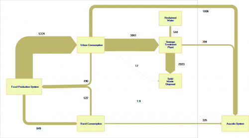
I quickly “translated” the above diagram to a Sankey diagram with flow values being actually to scale.
(click image to enlarge)
Here it is quite clear where the major phosphorus flows are located (from food production via urban consumption to sewage treatment plant and solid waste disposal: 2923 out of 5374 tons end up here). The other flows are comparatively small, with the phoshporous flow going directly to the aquatic system worth a mention. Two small flows in the center of the diagram are negligible, they are in fact so tiny in comparison to the major flows that they even don’t show up (or just as a hairline) here.
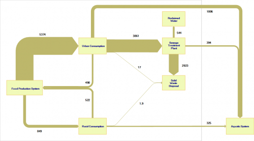
I have therefore added a minimum width of 1 px for small flows so that the annual 17 tons from urban consumption and the 1.9 tons from rural consumption to the solid waste disposal are at least visible (albeit not to scale with the other flows any more).
(click image to enlarge)
Final phosphorous sinks are solid waste disposal (landfill?) and the aquatic system.
